|
Instrument Page:
MPE-3D Pages
|
MPE-3D Instrumental
Characteristics:
Basic Overview
The instrument is based on a 2562 NICMOS-3
Rockwell array and can simultaneously obtain 256 H- or K-band spectra
at R = 1100 or 2100 from a square 16 x 16 pixel field on the sky.
The pixel size depends on the specifics of the telescope, but typically
ranges between 0.3" and 0.5" per pixel. On the 3.9 meter
Anglo-Austalian Telescope the nominal
pixel scale is 0.4" per pixel (see also comments under the section on
ROGUE).
The basic working principle for 3D
can best be illustrated by the following diagram
(from
Thatte
et al. 1994)
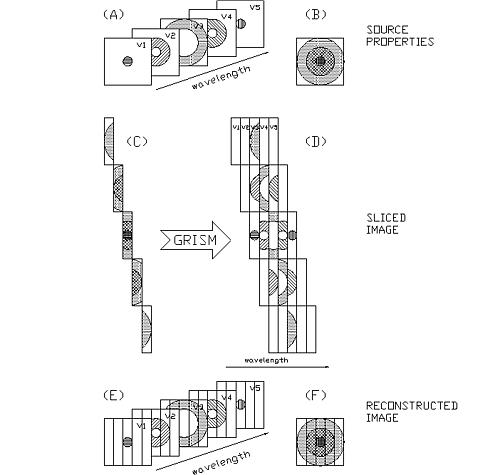
In this figure, an astronomical source has
a morphology which depends on wavelength (A). Its broadband morphology
is illustrated in (B). 3D
uses
an image slicer to "dissect" the source into 16 slitlets (5 of which are
depicted here) and to stack the slitlets on top of each other, forming
a pseudoslit (C). This pseudoslit is then passed through a grism,
dispersing it in wavelength and forming a two dimensional "image" of the
source (D), which is imaged on the detector. In post-observation
analysis this two dimensional format is converted into a data cube (E),
which can be collapsed to recover the broadband morphology (F).
Wavelength Coverage
3D has
a remotely controllable grism slide as part of its design. This slide holds
two grisms; thus, at any point in time the observer can choose between
the two grisms which have been installed for that run. Although
we have five grisms (see Table below), only two are installed for any given
run (to avoid loss of observing time resulting from a grism exchange).
Please note that the wavelength ranges in the Table below are not to be
viewed as absolute. Rather, the values used during a run may vary
by, typically, ±0.02 µm, owing to last minute adjustments
in the observatory prep room. Our stock of grisms is as follows:
3D's
Suite of Grisms
|
Grism
|
 low(µm) low(µm)
|
high(µm)
|
R=/
|
|
Hlow
|
1.48
|
1.78
|
1250
|
|
Hhigh
|
1.55
|
1.75
|
2100
|
|
K
|
1.94 |
2.41 |
1100
|
|
Kshort
|
1.95
|
2.18
|
2100
|
|
Klong
|
2.17
|
2.43
|
2100
|
Sensitivity
The total instrument transmission (excluding
of the telescope, but including the tip-tilt optics
the grism, and the filter is XX%. The quantum efficiency of the detector
itself is 65%. Overall, the sensitivity of
3D is given by
the values in the Tables below
Point
Source Continuum Sensitivity
|
Point Source magnitude
|
0.25 pixels
 |
0.4
pixels
|
|
Seeing
|
Seeing
|
|
H-band
|
K-band
|
0.5 |
1.0 |
1.5
|
0.5 |
1.0 |
1.5 |
|
15.5
|
15
|
80
160
|
310
620
|
690
1380
|
<60
60
|
120
240
|
270
540
|
|
16.5
|
16
|
480
960
|
1900
3800
|
4280
8560
|
190
380
|
740
1480
|
1670
3340
|
|
17.5
|
17
|
3000
6000
|
12000
24000
|
27100
54200
|
1200
2400
|
4700
9400
|
10600
21200
|
|
18.5
|
18
|
18900
37800
|
75500
|
|
7400
14800
|
29500
59000
|
66380
|
|
|
19.5
|
19
|
|
|
|
46700
93400
|
|
|
The numbers represent
integration times (in seconds) for a source of given broadband magnitude
for a S/N of 3. Total times include equal exposure on sky plus atmospheric
(and flux, if required) calibrator(s). Therefore, to arrive at a total
time one should multiply the above values by a factor which is no less
than 2.3 (larger values would be used for larger telescope offsets required
to attain blank sky positions, sources for which offset ROGUE
tracking may be time consuming, etc.) The numbers in the above Table refer
to 1 channel (at R = 1000) at a nominal wavelength of 1.64 µm
(H) or 2.15 µm (K).
Line
Flux in Extended Objects
|
Flux (erg/s/cm2/()2)
|
0.25pixels
|
0.4
pixels
|
|
H
|
K
|
H
|
K
|
|
3 x 10-15
|
160
|
80
|
60
|
30
|
|
1 x 10-15
|
1400
|
700
|
550
|
275
|
|
3 x 10-16
|
16000
|
8000
|
6200
|
3100
|
|
1 x 10-16
|
|
70400 |
55000
|
27500
|
The numbers represent
integration times required to achieve a S/N of 3 in 1 channel (at R
= 1000) at a nominal wavelength of 1.64 µm (H) or 2.15 µm
(K). Total times include equal exposure on sky plus atmospheric (and flux,
if required) calibrator(s). Therefore, to arrive at a total time one should
multiply the above values by a factor which is no less than 2.3 (larger
values would be used for larger telescope offsets required to attain blank
sky positions, sources for which offset ROGUE
tracking may be time consuming, etc.)
Integration Times
The minimum integration time is 0.3 seconds, while
the maximum integration is set by the extent to which sky emission lines
can be removed. This clearly depends on sky conditions but is typically
of order 60 seconds at H-band and 100 seconds at K-band.
ROGUE
3D incorporates
a fast tip-tilt image motion corrector, ROGUE
(Rapid Off-axis
GUider
Experiment).
This system employs a dichroic to separate the visible light from the NIR,
and uses 4 avalanche photo-diodes (APD's) to track a bright compact object
in the field. This object can either be a star or the program source itself,
depending on the source characteristics.
ROGUE
is capable of operating at 80 Hz for tracking
sources as faint as V=17. The field-of-view for ROGUE
is ±1.6' (at the AAT) from the program
object, and the movable pick-off mirror allows the observer to use any
sufficiently bright, compact source in that field. In addition,
ROGUE
incorporates
a feature which allows observers to choose between two pixel scales. At
the AAT these two scales are the nominal 0.4" per pixel, and the finer
0.25" per pixel.
This page was last modified on 10 November 1998.
|