3.2 IR / Submillimeter Astronomie /
IR / submillimeter Astronomy
|
|
Erste Beobachtungen erfolgten 2001 mit dem beugungsbegrenzten
Nahinfrarotinstrument CONICA und mit unserem Beitrag zum Testinstrument VINCI
des VLT-Interferometers, beide an ESOs Very Large Telescope auf Cerro
Paranal in Chile. Dies eröffnet neue Möglichkeiten für unseren Ansatz, wenige
Schlüsselfragen der Galaktischen und der extragalaktischen Astrophysik mit
neuen Instrumenten über den gesamten Infrarot- und Millimeterbereich
anzugehen. Beobachtungen mit höchster räumlicher Auflösung von Objekten im
frühen Universum werden ebenso möglich sein wie Studien naher Galaxien, mit
dem zusätzlichen Vorteil, dass Infrarotbeobachtungen verdeckenden Staub
durchdringen. Das feldabbildende Spektrometer SPIFFI für das VLT zielt auf
Beobachtungen bereits 2002. Sowohl CONICA als auch SPIFFI werden aus der
PARSEC-Entwicklung eines leistungsstarken Laserleitsterns für Beobachtungen
mit adaptiver Optik Nutzen ziehen. Weitere Projekte für 8m-Teleskope am Boden
sind eingeleitet. Für den vom Boden unzugänglichen Ferninfrarotbereich ist
FIFI-LS für das Flugzeugteleskop SOFIA in Bau, parallel zur umfangreichen
Entwicklung von PACS für ESA's Weltraumobservatorium Herschel. Wir
beschreiben im Folgenden erst die Projekte im nahen Infrarot und dann im
fernen Infrarot.
|
First light has been achieved in 2001
for the diffraction limited near-infrared instrument CONICA and for our
contribution to the VLT Interferometer test instrument VINCI, both at ESO's
Very Large Telescope on Cerro Paranal in Chile. This opens new opportunities
for our approach of tackling a few key questions of Galactic and
extragalactic astrophysics with novel instruments over the entire infrared to
millimeter wavelength range. Highest spatial resolution observations will be
possible of objects in the early universe as well as detailed studies of
nearby galaxies, with the additional advantage of penetrating obscuring dust
by observing in the infrared. The integral field spectrometer SPIFFI for the
VLT is aiming for observations already in 2002. Both CONICA and SPIFFI will
benefit from the PARSEC development of a powerful laser guide star to assist
adaptive optics observations. Further projects for ground based 8m class
telescopes
are underway. Instruments under development for the far-infrared wavelength
range, inaccessible from the ground, are FIFI-LS for the SOFIA airborne
telescope
and the major development of PACS for ESA's Herschel Space Observatory. We
describe below first the near-infrared projects and then continue to the
far-infrared.
|
|
|
|
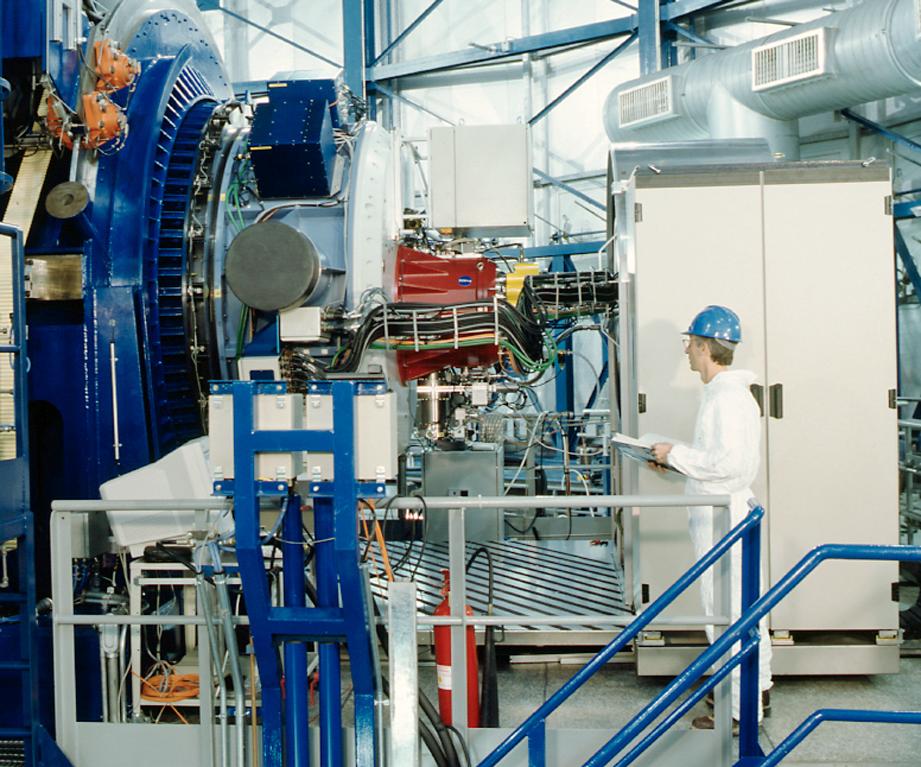
Abb. 3-4: CONICA (rot) und die adaptive Optik NAOS am
Nasmyth-Focus des VLT UT4.
Fig. 3-4: CONICA (red) and the
adaptive optics system NAOS mounted at the Nasmyth Focus of VLT UT4.
|
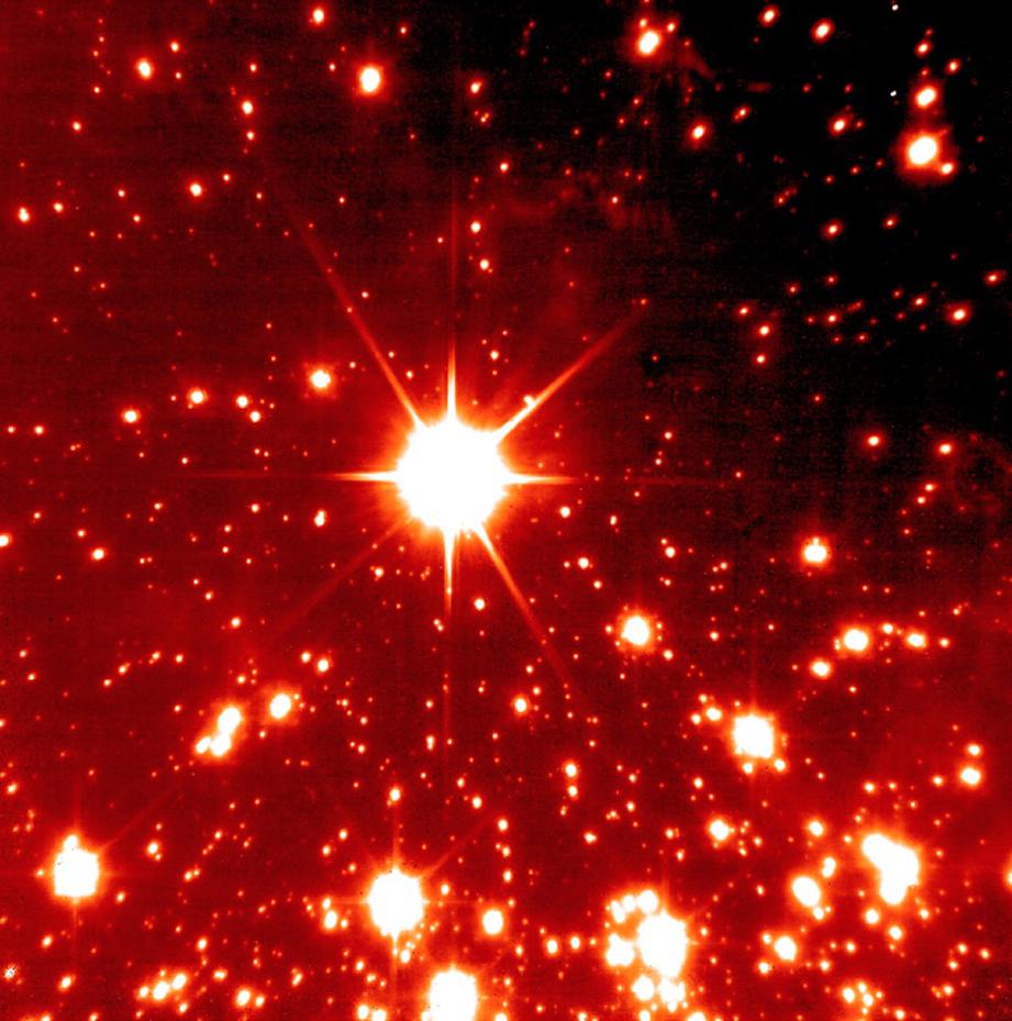
Abb. 3-5: Beugungsbegrenztes Bild des Sternhaufens NGC
3603, aufgenommen während der Inbetriebnahme von CONICA. Die fünf Minuten
belichtete Aufnahme erreicht K » 22 mag.
Fig. 3-5: Diffraction limited image
of the star cluster NGC 3603 taken during commissioning of CONICA. The five
minute exposure reaches K » 22 mag.
|
|
Im ersten Halbjahr wurde CONICA, eine
Kombination aus Nahinfrarot-Kamera und Spektrograph für beugungsbegrenzte
Beobachtungen am VLT, zusammen mit dem adaptiven Optik System NAOS am Observatoire
de Paris abschließend getestet. Nachdem beide Instrumente Anfang September
den Eingangstest von ESO bestanden haben, wurden sie zum Paranal verschickt,
wo im Oktober und November die Integration und Tests stattfanden. Am 29.
November wurde die Kombination von CONICA und NAOS erstmals am VLT eingesetzt
und bereits eine Strehlzahl von 70% im K-Band erreicht (Abb. 3-4,
Abb. 3-5). Weitere Tests sind für Ende Januar und Ende März 2002
geplant. Ab Herbst 2002 soll das Instrument allen Astronomen zur Verfügung
stehen.
|
CONICA, a combination of near infrared
camera and spectrograph for diffraction limited observations at the VLT, went
through the final tests together with the adaptive optics system NAOS at the
Observatoire de Paris during the first half of the year. After passing ESO's preliminary acceptance test in early September,
CONICA and NAOS have been shipped to Paranal, and have been integrated and
tested in October and November. First light at the VLT was achieved on 29
November, and a K-band
Strehl ratio of 70% has been reached already (Fig. 3-4, Fig. 3-5).
Commissioning continues in January and March 2002. The instrument
will be made available to the astronomical community starting in fall 2002.
|
|
Mit LISA, der am MPE gebauten Nahinfrarot-Kamera
für das VLT-Test-Interferometer VINCI, wurden am 17. März 2001 erstmals
Interferenzen gesehen, wobei zwei Siderostaten mit 40 cm Öffnung und die
Verzögerungsstrecken des VLT-Interferometers benutzt wurden. Erste
Interferenzen unter Verwendung der beiden VLT 8m-Teleskope UT1 und UT3 wurden
im Oktober 2001 gemessen.
|
LISA,
the MPE built near infrared camera for the VLT-interferometer test unit
VINCI, has been successfully used to detect first fringes on 17 March 2001,
using two 40 cm siderostats and the VLT interferometer delay lines. First
fringes with the VLT 8m telescopes UT1 and UT3 have been obtained in October
2001.
|
|
Das abbildende Spektrometer SPIFFI kann in einer
einzelnen Aufnahme die Spektren von 1024 Bildpunkte messen. Dadurch wird es
möglich, in bisher unerreichter Effizienz und Qualität die spektralen
Eigenschaften
von komplexen Objekten zu bestimmen. Das Instrument wird voraussichtlich
erstmals im Jahr 2002 am Very Large Telescope (VLT) der Europäischen
Südsternwarte
(ESO) in Betrieb genommen. Nach einer ersten Testphase wird SPIFFI zusammen
mit einer adaptiven Optik betrieben werden, die zur Zeit an der ESO in
Entwicklung ist. Die Kombination des abbildenden Spektrometer SPIFFI mit der
adaptive Optik wird SINFONI genannt und wird den europäischen Astronomen ab
2004 angeboten. Nach der Unterzeichnung des Vertrags mit ESO konnten wir in
diesem Jahr die Konstruktion des Instrumentes optimieren und abschließen und
mit der Herstellung beginnen.
|
With a single exposure, the imaging
spectrometer SPIFFI can measure the spectra of 1024 field points. This
multiplex advantage allows us to determine in unprecedented efficiency and
quality the spectral properties of extended objects. We will put the
instrument
into operation for the first time in 2002 at the Very Large Telescope (VLT)
of the European Southern Observatory (ESO). After a first test period, SPIFFI
will then be operated together with an adaptive optics system presently
developed
at the ESO. The combination of SPIFFI and this adaptive optics is named
SINFONI, and will be offered to the European community in 2004. After the
signature of our contract with the ESO we optimized and completed the design
of the instrument this year and started manufacturing.
|
|
|
|
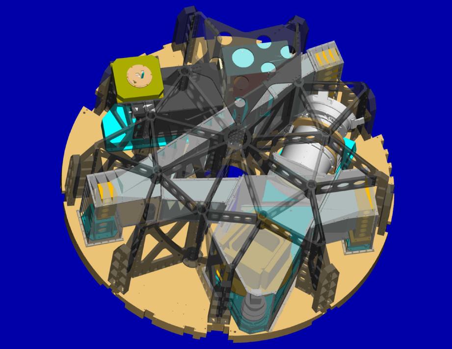
Abb. 3-6: Links: Opto-mechanische Komponenten von
SPIFFI (Gesamtdurchmesser 1.2 m). Die dunkle Struktur dient zur Versteifung
des Instruments. Alle Komponenten werden zum Betrieb auf eine Temperatur von
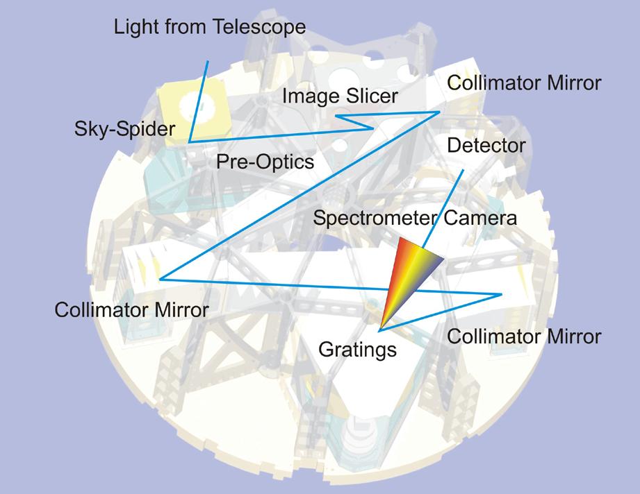
-196°C abgekühlt. Rechts: Schema des Strahlengangs. Das Licht tritt oben
links in das Instrument ein, und folgt dann einem großen "Z" zum
Reflexionsgitter in der unteren Bildhälfte. Der Detektor befindet sich rechts
oberhalb der Bildmitte.
Fig. 3-6: Left: Opto-mechanical
components of SPIFFI (total diameter 1.2 m). The purpose of the dark structure
is to increase the stiffness of the instrument. All components are cooled to
a temperature of -196°C for operation. Right: Schematic drawing indicating
how the light enters the instrument at the top left, and follows a large "Z"
to the reflection grating at the bottom of the image. The detector is located
to the top right of the image centre.
|
|
Alle wesentlichen Komponenten von SPIFFI werden bis
Jahreswechsel 2001/2002 geliefert sein. Das Herzstück ist der Bildzerleger,
der das Gesichtsfeld mit 32 Spiegeln in Streifen schneidet und dann mit
weiteren 32 Spiegeln zu einem Spalt anordnet. Das Licht wird dann in einem
Gitterspektrometer
dispergiert und mit einem Detektorarray nachgewiesen. Die Kollimatorspiegel
des Spektrometers werden aus nickelbeschichtetem Aluminium diamantgedreht.
Um Wellenlängen von 1 - 2.5 µm optimal abzudecken, kommen in SPIFFI vier
verschiedene Reflexionsgitter zum Einsatz, die speziell hierfür optimiert und
angefertigt wurden. Die Kamera des Spektrometers besteht aus insgesamt sechs
Linsen mit einem Durchmesser von bis zu 160 mm. Da normale Gläser für
infrarotes Licht nicht geeignet sind, werden diese Linsen aus
Bariumfluorid-Kristallen
und einem speziellen Infrarotglas hergestellt. Aufgrund der besonderen
physikalischen
und chemischen Eigenschaften dieser Materialien musste eine spezielle
Antireflexbeschichtung entwickelt werden. Da das Instrument zum Betrieb mit
flüssigem Stickstoff auf ~196°C abgekühlt wird, befinden sich alle
optischen und mechanischen Komponenten (Abb. 3-6) in einem Kryostaten.
|
All major components of SPIFFI will be
finished by the turn of the year. Its heart is the image slicer, which slices
the image with the help of 32 mirrors and then rearranges the light with
additional 32 mirrors in the form of a long slit. The light is then dispersed
in a grating spectrometer and finally detected in a state of the art detector
array. The collimating mirrors of the spectrometer are diamond turned from
nickel plated aluminium. In order to optimally cover a wavelength range from
1 - 2.5 µm, we implement four reflection gratings, all specially optimised
and manufactured for SPIFFI. The spectrometer camera is made from six lenses
with a diameter of up to 160 mm. Because normal glasses are inappropriate for
near-infrared light, these lenses are made from barium fluoride crystals and
a special infrared glass. Because of the extraordinary physical and chemical
properties of these materials, we had to initiate a new development of an
antireflection coating. The instrument needs to be cooled to a temperature of
~196°C for operation. This is why all optics and mechanics
(Fig. 3-6) is enclosed in a cryostat.
|
|
Das Large Binocular Telescope (LBT) ist
ein doppeltes 8.4 Meter Teleskop in Bau auf Mt. Graham in Arizona, USA.
Der Testaufbau der Teleskopstruktur fand in den Integrationseinrichtungen von
Ansaldo Energia S.p.A. nahe Mailand statt. Das Teleskopgebäude ist
fertiggestellt,
und die Inneneinrichtung wird zur Zeit aufgebaut. Der erste der zwei
Hauptspiegel wird poliert, und ein Prototyp für den adaptiven Sekundärspiegel
hergestellt. Das "first light" des LBT, an dem fünf deutsche Institute mit
einem 25%-Anteil beteiligt sind (darunter auch das MPE), wird für März 2004
erwartet. Als Teil des MPE-Beitrags zum Projekt stellen wir 14 steife
Unterstützungspunkte
für die beiden Hauptspiegel her. Der erste Satz Unterstützungspunkte ist
hergestellt
und getestet und wird Anfang 2002 nach Arizona verschickt. Der zweite Satz
ist derzeit in Herstellung.
|
The Large Binocular Telescope (LBT),
a twin 8.4 meter telescope being erected on Mt. Graham in Arizona, U.S.A.,
completed pre-assembly of the telescope structure at the integration
facilities at Ansaldo Energia S.p.A., near Milan. The construction of the
telescope
enclosure is complete, internal furnishing is in progress. The first of the
two primary mirrors is being polished. A prototype of the adaptive secondary
mirror is under fabrication. First light for the LBT, in which five German
institutes, including MPE, hold a 25% share, is expected in March 2004. As
part of MPE's contribution to the project, the institute is fabricating 14
hard points, which provide the stiff supports for the two primary mirrors.
The first set of hard points has been fabricated and tested and will be
shipped to Arizona in early 2002. The second set is presently under
production.
|
|
LUCIFER ist eine Kombination von Nahinfrarot-Kamera
und Spektrograph für "seeing"-
und beugungsbegrenzte Beobachtungen mit dem LBT. Das Instrument wird von
einem deutschen Konsortium unter Führung der Landessternwarte Heidelberg
gebaut, MPE liefert dazu die Multi-Objekt-Einheit (MOS). Diese Einheit
besteht aus einem stationären Magazin, in dem zehn Spalt- und
Gesichtsfeld-Masken
untergebracht werden können, einem auswechselbaren Magazin für 23
Multi-Spalt-Masken (die für jede Beobachtung neu angefertigt werden müssen),
einem System, das den Wechsel des Magazins bei kaltem Kryostaten (~77 K)
erlaubt und einem kryogenen Roboter, der die Masken in LUCIFER handhabt.
Außerdem werden zwei Hilfskryostaten benötigt, einer zum Vorkühlen der neu
gefertigten Masken, der andere zur Aufnahme der aus LUCIFER entfernten
Masken. Sowohl LUCIFER als auch die Hilfskryostaten sind mit Schleusen von 32
cm freiem Durchmesser ausgestattet, die ausreichend groß sind um die
gefüllten Magazine hindurch zu schieben. Im Herbst 2001 wurde mit der
Konstruktion dieses Systems begonnen, sie soll im Februar 2002 abgeschlossen
werden. Erste Komponenten wurden bereits bestellt, mit der Herstellung der
Teile wird Anfang 2002 begonnen.
|
LUCIFER
is a near infrared camera and spectrograph for seeing and diffraction limited
operation at the LBT which is being built by a German consortium lead by the
Landessternwarte at Heidelberg. MPE contributes the (cryogenic) multi-object
(MOS) unit for this instrument. The MOS unit consists of a stationary cabinet
housing ten long slit masks and field limiting masks, an exchangeable cabinet
for 23 multi-slit masks, a system to exchange the multi-slit masks in their
cabinet with LUCIFER at operating temperature (about 77 K), and a
cryogenic
robot to transport the masks from their storage place in the cabinet to the
telescope focal plane. Two auxiliary cryostats are required, one for
pre-cooling newly made masks, the other one for accommodating previously used
masks when removed from the LUCIFER cryostat. The LUCIFER cryostat as well as
the auxiliary cryostats are equipped with identical air-locks consisting of
32 cm clear diameter ultra high vacuum valves, large enough to accept the
mask cabinets. In fall 2001 the final design of the MOS unit has started and
will be finished in early 2002. First components have been ordered,
manufacturing of the components starts beginning of 2002.
|
|
PARSEC, der Laser für das Laserleitsternsystem
des VLT, hat im letzten Jahr wesentliche Fortschritte gemacht. Die vorläufige
Entwurfsprüfung im April war erfolgreich, nächster größerer Schritt ist der
Laserauswahltest im Januar 2002. An diesem entscheidenden Punkt muss gezeigt
werden, dass der vorgeschlagene Entwurf mit minimalem Risiko verbunden ist.
Zur Vorbereitung wurde ein Prototyplaser gebaut, der zur Zeit im Labor
getestet wird. Hervorzuheben ist, dass eine Ausgangsleistung von 11.5 W
erzielt wurde, doppelt so viel wie bei allen bisherigen Dauerstrichlasern bei
589 nm und bereits in Einklang mit den Spezifikationen. Um dieses
Ergebnis zu erzielen, wurde die Farbstoffpumpe bei einem Druck von fast 30
Bar betrieben und jeder der beiden Farbstoffstrahlen im Verstärker mit einer
Leistung von 30 W aus Argon-Ionenlasern gepumpt. Bei ähnlichem
Fortschritt verspricht das nächste Jahr ereignisreich zu werden.
|
PARSEC,
the laser for the VLT Laser Guide Star Facility, has made significant
progress during the last year. It passed the Preliminary Design Review in
April and is now approaching the next milestone, the Laser Selection Test in
early January 2002. This is the critical point at which it is necessary to
demonstrate that there is only a minimal risk associated with the proposed
design. During preparation, a prototype laser has been built and is now
undergoing tests in the lab. The most outstanding achievement is to have
reached an output power of 11.5 W, twice that which has been possible on
any other continuous wave 589 nm laser and already meeting the Technical
Specification. To achieve this result, the dye circulator was operated at a
pressure of nearly 30 bar, and each of the 2 dye jets in the amplifier
was pumped with 30 W of power from an argon ion laser. If progress
continues
in a similar way, then the next year promises to be very exciting.
|
|
Als größere Neuentwicklung für das LBT und/oder VLT
untersuchen wir den kryogenen Multi-Objekt-Spektrographen CROMOS in
Zusammenarbeit zwischen MPE und der Universitätssternwarte München. CROMOS
ist als Nahinfrarot-Spektrograph mit kleinen, frei beweglichen
Integralfeld-Einheiten (IFUs) konzipiert. Innerhalb des Gesichtsfeldes von 4
bis 7 Bogenminuten sind 20 bis 40 IFUs mit je 25 bis 50 Bildelementen von 0.3
Bogensekunden Durchmesser frei beweglich. Das von den IFUs aufgenommene Licht
wird über optische Fasern zum Eintrittsspalt transportiert. Danach wird die
Strahlung durch Strahlteiler in die drei Bänder J, H und K aufgeteilt und je
einem dezidierten Spektrographen zugeführt, so dass die Spektren der drei
Wellenlängen-Bänder gleichzeitig mit einer spektralen Auflösung von etwa 5000
aufgezeichnet werden können.
|
As a major new development for the LBT
and/or VLT we study the cryogenic multi-object spectrograph CROMOS in
a collaboration of MPE and the Universitätssternwarte München. CROMOS is a
near-infrared spectrograph making use of deployable mini integral-field units
(IFUs). Within the field of view of 4 to 7 arcmin, 20 to 40 IFUs with 25 to
50 image elements of 0.3 arcsec diameter each can be freely positioned. The
light received by the IFUs is transferred to the entrance slit of a
three-channel spectrograph by optical fibers. The light is then separated by
beam splitters into the three wavelength bands J, H and K and is fed into
three dedicated spectrographs, so that the spectra in the three bands can be
recorded simultaneously with a spectral resolving power of about 5000.
|
|
Im Rahmen der Forschungs- und Entwicklungsarbeiten für
CROMOS haben wir die Bewertung aufgeweiteter Glasfasern fortgesetzt und einen
Prototyp des Positionierroboters, der komplexesten Komponente des Instruments,
gebaut und getestet. Eine erste Version der Steuer-Programme für den Roboter
wurde entwickelt und getestet. Da das Drehmoment der bisher benutzten
Schrittmotoren für eine Komponente des Roboters nicht ausreicht, wurde nach
alternativen Antrieben gesucht. Eine mögliche Lösung sind Servo-Motoren,
deren Kryotest steht aber noch aus. Im Herbst begann die Arbeit an den IFUs
mit Versuchen an Glasfasern und Standard-Mikrolinsen-Arrays. Eine erste
optische Auslegung des Instruments erlaubt die Abschätzung der Größe des
erforderlichen Kryostaten und die Identifikation möglicher Probleme des
Konzepts.
|
As part of the research and
development for CROMOS we have continued evaluation of flared fibres and
constructed
and tested a prototype positioning robot, the most complex component of the
instrument. A first version of the control software required to position the
IFUs has been developed and tested. New drive concepts for the robot are under
study because the torque of the stepper motors previously used is too low.
Servo motors seem to be a good alternative, but are still awaiting tests at
liquid nitrogen temperature. In fall work on the IFUs has started with tests
and measurements on fibers and off-the-shelf micro-lens arrays. We have set
up a first optical layout of the complete system which helps to define the
instrument size and to identify possible problems in the concept.
|
|
Wir haben an zwei von ESA unterstützten Studien zur Konzeption
des Nahinfrarotspektropgraphen des Next Generation Space Telescope
(NGST)
teilgenommen. Die erste Studie für den Entwurf eines feldabbildenden
Spektrographen baut auf dem erfolgreichen Entwurf der Bildfeldzerleger in den
3D und SPIFFI-Instrumenten des MPE auf. Die Ergebnisse wurden im November bei
einem Treffen bei ESO präsentiert. Die zweite Studie untersuchte einen
Entwurf mit Mikrospiegelmatrizen, die umkonfigurierbare Spalte in der
Fokalebene für Multiobjektspektroskopie über ein 3´x3´ Gesichtsfeld erzeugen.
MPE is auch an einem von der Astrium GmbH geführten Konsortium für eine
Phase-A-Studie des NGST-Spektrographen beteiligt.
|
MPE participated in two ESA-sponsored
studies exploring concepts for the near infrared spectrograph for the
Next Generation Space Telescope (NGST). The first study
involved the design of an Integral Field Spectrograph, based upon the very
successful design of the image slicer used in the MPE 3D and SPIFFI
instruments.
The results were presented at a meeting held at ESO in November. The second
study explored a design based on a micro-mirror array which provides
re-configurable slits in the focal plane for multi-object spectroscopy over a
3'×3' field of view. As part of a consortium led by Astrium GmbH,
MPE is also involved in a proposal to carry out the Phase A study of the NGST
spectrograph.
|
|
Für das Herschel Space Observatory der ESA, das
im Frühjahr 2007 gestartet wird, trägt das MPE als PI-Institut innerhalb
eines europäischen Konsortiums aus 14 Instituten in 6 Ländern die
Verantwortung
für den Bau und Betrieb eines der drei Fokalebeneninstrumente. PACS
(Photodetector Array
Camera & Spectrometer) ist ein abbildendes, kombiniertes
Photo 45/ Spektrometer
für den Wellenlängenbereich 57-210 µm. Im Sommer wurde von ESA Alcatel
(Cannes) als Hauptauftragnehmer für das Herschel/Planck-Projekt ausgewählt,
damit erweitern sich die Arbeiten von der Instrumenten- auf die Systemebene.
|
For
the Herschel Space Observatory, an ESA cornerstone mission to be
launched in spring 2007, MPE as the PI-institute in a European consortium of
14 institutes from 6 countries is taking the lead in the construction and
operation of one of the three focal plane instruments. PACS (Photodetector
Array Camera & Spectrometer) will be a combined imaging photo /
spectrometer for the wavelength range 57-210 µm. This summer ESA selected
Alcatel (Cannes) as the Prime Contractor for the Herschel/Planck project. Our
activities now extend from instrument to system level.
|
|
Im Photometriebetrieb wird PACS ein Gesichtsfeld von
~ 1,75' x 3'
gleichzeitig in zwei Wellenlängenbändern, 60-85 oder 85-130 µm und 130-210
µm, abbilden. Dazu werden zwei
Bolometer-Arrays mit 16x32 bzw. 32x64 Pixel eingesetzt. Die
überlegene Empfindlichkeit und Winkelauflösung wird vor allem bei tiefen Durchmusterungen
zum Tragen kommen, die uns einzigartige Informationen über die Entstehung von
Galaxien im frühen Universum geben werden sowie neue Einblicke in die
Sternenstehung im Inneren von Molekülwolken. Eine Kombination aller photometrischen
Bänder von Herschel wird eine weitgehende Identifizierung hochrotverschobener,
leuchtkräftiger Quellen erlauben, die in der Folge durch Spektroskopie
genauer charakterisiert werden können.
|
In
photometry mode PACS will image a field-of-view of ~ 1.75' x 3' simultaneously in two wavelength bands, 60-85 or 85-130 µm and
130-210 µm, respectively. This is facilitated by two bolometer arrays with 16x32 and 32x64 pixel, respectively. The superior
sensitivity and angular resolution will be crucial, particularly for deep
surveys which will give us unique information about the formation of galaxies
in the early Universe as well as new insight into star formation inside
nearby molecular clouds. A combination of all photometric bands of Herschel
will allow a fairly reliable identification of highly redshifted, luminous
sources which then can be characterized in detail by follow-up spectroscopy.
|
|
Im Spektroskopiemodus wird PACS ein Gesichtsfeld von ~
50"x50"
abdecken und dabei für jeden der 5x5 Bildpunkte gleichzeitig ein
Linienspektrum mit
einer Auflösung von ~170 km/s erzeugen. Dies wird ermöglicht durch
einen optischen Bildfeldzerleger in Verbindung mit einem Gitterspektrographen.
Als Detektoren dienen zweidimensionale Detektorarrays aus 25x16
gedrückten Germanium-Photoleitern. Damit sind z.B. detaillierte
Untersuchungen an Galaxien und ihren Kernregionen möglich bis hin zu einer
Diskriminierung der Energiequellen hochrotverschobener, ultraleuchtkräftiger
Objekte.
|
In spectroscopy mode PACS will cover a
field-of-view of ~ 50"x50" and simultaneously produce a line spectrum for
each of the 5x5 spatial pixels with a spectral
resolution of ~170 km/s. This is made possible by an optical image
slicer which is feeding a grating spectrograph. As detectors we use
two-dimensional arrays of 25x16 stressed
germanium photoconductors. This allows, e.g., detailed studies of galaxies
and their nuclei including a discrimination of the energy sources in highly
redshifted, ultraluminous objects.
|
|
Die Konstruktion des Instruments mit seiner hochkomplexen
Optik wurde in enger Zusammenarbeit mit Kayser-Threde (München) als
Hauptauftragnehmer für die kryogene Fokalebenen-Einheit erfolgreich
abgeschlossen,
einschließlich der Integration der im Vorjahr neu hinzugekommenen
Bolometereinheit. Die Fertigung der Struktur hat kürzlich begonnen.
|
The
design of the instrument with its highly complex optics has been done in
close collaboration with Kayser-Threde (Munich) as the main contractor for
the cryogenic focal plane unit. The integration of the bolometer unit which
came as an addition during the previous year has been fully accomplished. The
manufacture of the structure has started recently.
|
|
Die zweidimensionalen Arrays gedrückter
Ge:Ga-Detektoren, bestehend aus 25 Modulen zu 16 Pixel (Abb. 3-7) werden
in
Zusammenarbeit mit ANTEC (Kelkheim) entwickelt. Inzwischen konnten alle Module
für das Qualifikationsmodell - bis auf die Integration der kryogenen
Ausleseelektronik - fertiggestellt werden. Kryogene Schütteltests wurden am
MPE erfolgreich durchgeführt. Die Quantenausbeute der Detektoren wurde
gemessen; sie lag bei oder oberhalb der geforderten 30%. Die kryogene
Ausleseelektronik
für die Detektoren, die bei IMEC (Leuven) entwickelt wird, war eine der
größten Herausforderungen des Projektes. Kürzlich konnte erstmals
demonstriert werden, dass die strengen Anforderungen an Rauschen, Linearität
und Dissipation erfüllt werden können.
|
The
two-dimensional Ge:Ga detector arrays, consisting of 25 modules of 16 pixels
(Fig. 3-7), are developed in
collaboration with ANTEC (Kelkheim). Meanwhile,
all modules for the qualification model have been manufactured and are
waiting for the integration of the cryogenic readout electronics. The quantum
efficiency of the detectors has been measured; the quantum efficiency was at
or above the PACS requirement of 30%. The cryogenic readout electronics for
the detectors which is developed at IMEC (Leuven) has always been considered
to be one of the major challenges of this project. Recently they could be
demonstrated - for the first time - to fulfill the stringent requirements on
noise, linearity and dissipation.
|
|
Die Entwicklung der Bolometereinheit bei CEA (Saclay)
hat sowohl im Bereich der Bolometer selbst als auch des 0,3 K Kühlers
wichtige Meilensteine erreicht. Die Fertigung der 16x16-Subarrays und ihre
Verbindung mit der 0.3 K Puffer/Multiplexer-Elektronik für die
Qualifikationsmodelle wurde abgeschlossen; erste Tests laufen zur Zeit. 4x2
Subarrays konnten zu einem 64x32 Pixel Fokalebenen-Array einschließlich der
2 K Pufferverstärker integriert werden (Abb. 3-7). Dies ist der
größte Detektor, der je für den Ferninfrarotbereich gebaut wurde.
|
The
development of the bolometer unit at CEA (Saclay) has reached important
milestones both in the area of the bolometers proper but also for the the
0.3 K sorption cooler. The manufacture of the 16x16 subarrays
and their bonding to the 0.3 K buffer/multiplexer electronics has been
completed; first tests are presently running. 4x2 subarrays
have been successfully integrated into a 64x32 pixel
focal plane array, including the 2 K buffer amplifiers (Fig. 3-7).
This is the largest detector ever built for the far infrared wavelength
range.
|
|
|
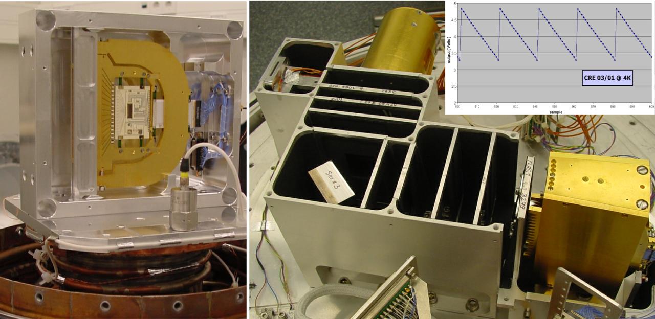
Abb 3-7: Links: Ein PACS Ge:Ga-Detektormodul mit
integrierter kryogener Ausleseelektronik, eingebaut im
Schüttelkyrostaten. Durch Schütteln im Testlabor des MPE mit bis zu 30g bei
einer Temperatur von 4 K wird sichergestellt, dass die Detektormodule
die starken Vibrationen während des Raketenstarts schadlos überstehen.
Rechts: Fotografie des Testaufbaus für die Detektormodultests am MPE. Der
Aufbau besteht aus einem Schwarzkörper (im Bild oben), einem Flachspiegel
(unten links), mehreren Filtern bzw. Abschwächern und dem Detektormodul
(unten rechts). Der Bildausschnitt rechts oben zeigt Integrationsrampen, die
mit Hilfe der kryogenen Ausleseelektronik bei einer Temperatur von 4 K
gewonnen wurden.
Fig. 3-7: Left: One PACS Ge:Ga
detector module with integrated cryogenic readout electronics mounted inside
the vibration test cryostat. Vibration tests at the MPE environmental test
lab up to levels of 30g at temperature of 4 K ensure that the PACS
detectors will survive the high vibrational loads during launch without
damage. Right: Test set-up for the detector module tests at MPE. The set-up
consists of a blackbody source (upper part of the image), a flat mirror
(lower left), several filters/attenuators and the detector module (lower
right). The inset shows integration ramps obtained with the cryogenic readout
electronics operated at 4 K.
|
|
Als wichtige Untereinheiten der Fokalebenen-Einheit werden
am MPIA (Heidelberg) der Chopper und bei CSL (Liége) die Gitterbaugruppe
entwickelt. Beide stellen kryogene Präzisionsmechanismen dar, für die
Entwicklungsmodelle
erfolgreich getestet wurden. Für den Chopper wurden spezielle
Kreuzfedergelenke entwickelt, die über die Dauer der Mission mehr als 30
Millionen
Lastzyklen überstehen müssen. Beim Gitterantrieb konnte gezeigt werden, dass
damit eine Positionierung mit der erforderlichen Genauigkeit von einigen
Bogensekunden erreicht werden kann. Die Entwicklung der Ingenieurmodelle für
die warmen Elektronikeinheiten bei unseren Partnern IAC (Teneriffa), IFSI
(Rom) und CSL (Liége) ist nahezu abgeschlossen; Tests auf Instrumentenebene
werden im März 2002 am MPE aufgenommen.
|
Two important subunits of the focal
plane unit, the chopper and the grating assembly, are being developed at MPIA
(Heidelberg) and CSL (Liége), respectively. Both represent high-precision
cryomechanisms for which development models have been successfully tested.
For the chopper, special flexural pivot elements have been developed which
have to survive more than 30 million load cycles over the duration of the
mission.
The grating drive has been demonstrated to reach the required positioning
accuracy
of several arc seconds. The development of the engineering models for the
warm electronics units by our consortium partners, IAC (Tenerife), IFSI
(Rome) and CSL (Liége), is nearly finished; instrument level tests will start
at MPE in March 2002.
|
|
Die Charakterisierung und Eichung des Instruments erfolgt
in der Verantwortung des MPE. Inzwischen wurde die Definition aller
benötigten Eich- und Testeinrichtungen weitgehend abgeschlossen und mit der
Entwicklung spezieller Messaufbauten begonnen. Der Auftrag für den Bau des
großen Testkryostaten zur Eichung des Gesamtinstrumentes wurde vergeben.
|
MPE is responsible for the complete
characterization and calibration phase of the instrument. We have largely
completed definition of the necessary test and calibration equipment.
Meanwhile design and development of special set-ups were started. The
contract for the construction of the large test cryostat for the calibration
of the integrated instrument has been placed.
|
|
MPE beheimatet auch das Instrument Control Centre (ICC)
für PACS. Als eines der Kompetenzzentren für Herschel ist das ICC
verantwortlich für Softwareentwicklung, Eichung und Betrieb von PACS. Das
ICC-Team am MPE konnte vervollständigt werden und wird weiter verstärkt durch
Mitarbeiter anderer Konsortiumsinstitute, die in dieser frühen Phase an ihren
Heimatinstituten verbleiben, aber zwei Jahre vor Start ans MPE kommen werden.
Zur Zeit arbeiten die Softwareingenieure und Wissenschaftler des ICC unter
anderem an Entwurf und Verwirklichung der Softwaresysteme (z.B. für eine
erste schnelle Analyse und für interaktive Analyse), der Definition der
Anforderungen für die Eichung und den Kommandoprozeduren für das Instrument.
|
MPE also hosts the Instrument Control
Centre (ICC) for PACS. As one of the centres of competence of the Herschel
ground segment the ICC is responsible for software development, calibration
and operation of PACS. We have been able to complete the MPE ICC team,
augmented by colleagues from the other consortium institutes, who at this
early phase are located at their home institutes but will be co-located at
MPE two years before launch. Present work of the ICC software engineers and
scientists includes design and implementation of software packages (like the
quick look analysis or interactive analysis systems), the definition of the
calibration requirements and the definition and implementation of instrument
command procedures.
|
|
MPE ist mit SOFIA (Stratospheric Observatory for Infrared Astronomy)
weiterhin aktiv an
der Flugzeug gestützten Astronomie beteiligt. Mit den 2001 erzielten
Fortschritten
liegt das SOFIA-Projekt im konsolidierten Zeitplan (erster Flug 2004). Das
aus Deutschland stammende Teleskop nähert sich seiner Fertigstellung. Die
Integration der ersten Untersysteme wird zu Beginn des nächsten Jahres
erfolgen. Am MPE entwickeln wir mit FIFI LS (Field-Imaging Far-Infrared Line
Spectrometer) eines der beiden deutschen Instrumente der ersten Generation
für SOFIA. Um eine maximale Beobachtungseffizienz zu gewährleisten, wird
erstmals für Beobachtungen im ferninfraroten Bereich ein abbildendes
3D-Spektrometer aufgebaut. Das Instrument besitzt zwei unabhängige
Gitterspektrometer
mit mittlerer Auflösung (R~1700), welche zwei großflächige Ge:Ga
Detektorarrays von jeweils 25x16 Pixel ausleuchten. Wir haben eine Methode
entwickelt, große Pixelstapel gleichmäßig unter Druck zu setzen und sie damit
für den Ferninfrarotbereich empfindlich zu machen. Erste Tests zeigen eine
gute und gleichmäßig verteile Quanteneffizienz von 30%.
|
MPE is continuing its active involvement in airborne astronomy with
SOFIA (Stratospheric Observatory for Infrared Astronomy). The
SOFIA project is proceeding on a consolidated schedule (first flights 2004)
with significant progress during 2001. In particular, the German telescope
assembly is close to completion and the first sub-system integration should
occur early next year. At MPE we are developing one of the two first
generation German instruments for SOFIA: FIFI LS (Field-Imaging Far-Infrared
Line Spectrometer). To accomplish maximum observing efficiency we use for the
first time in the far-infrared an integral field spectrometer with two
independent, separate medium resolution (R~1700) grating spectrometers with
common entrance optics feeding two large format Ge:Ga arrays of 25x16 pixel
each. At MPE we have successfully designed a practical method to stress
uniformly a large stack of Ge:Ga pixels for operation in the far-infrared.
Initial testing shows a good and evenly distributed quantum efficiency of
30%.
|
|
Mit den beiden Spektrometern kann ein Objekt gleichzeitig
in den Wellenlängenbereichen von 42-110 µm und 110-210 µm beobachtet werden.
In diesem Jahr konnte das optische Design für FIFI LS abgeschlossen und mit
der Beschaffung der Komponenten begonnen werden. Mit einem Bildfeldzerleger
wird ein Datenkubus (spektrale- und Ortsinformation) gewonnen, wobei
gleichzeitig für jedes der 25 räumlichen Pixel der Geschwindigkeitsbereich
von 1500 km/s um eine ausgewählte Spektrallinie abgedeckt wird. Im Zuge der
bevorstehenden
Lufttauglichkeitsprüfung der FAA haben wir die Konstruktion des Kryostaten,
der optischen Bank und der Halterstruktur am SOFIA Teleskop abgeschlossen
(Abb. 3-8). Eine vollständige finite Elementeanalyse aller tragenden
Teile wurde durchgeführt, ebenso wie detaillierte Designstudien und erste
Tests der kritischen Tieftemperaturmechanik. Nicht zuletzt haben wir begonnen,
die vielen kritischen Elektronikkomponenten für FIFI LS zu entwerfen und zu
testen.
|
With the two spectrometers we can
simultaneously observe an object in the wavelength bands of 42-110 µm and
110-210 µm in 1st or 2nd diffraction order, respectively. This year, we have
finalized the FIFI LS optics and begun the procurement of optic components.
Using an image slicer, an entire data cube (spectral and spatial information)
is obtained; we will instantaneously cover a velocity range of 1500 km/s
around the selected spectral line for each of the 25 spatial pixels. As we
near our airworthiness design review, which is required by the FAA to fly, we
continued the design of the cryostat with optical bench and the mounting
structure for the SOFIA telescope (Fig. 3-8). In particular, a complete
finite-element analysis of all structural parts has been carried out, as well
as a detailed design study and initial testing of the critical
cryo-mechanisms. In addition, we have begun the design and testing of many of
the critical FIFI LS electronics.
|
|
Forschungsarbeiten für die Entwicklung eines Photoleiter-Detektorarrays
aus n-leitendem Galliumarsenid wurden fortgesetzt. Solche
Ferninfrarot-Detektoren würden bei einer Betriebstemperatur von 1.8 K
bis 300 µm Wellenlänge empfindlich sein und könnten aufgrund ihrer
monolithischen Bauweise die Verwirklichung großer Arrays zulassen. Dieses
Ziel soll mit einem Detektortyp verwirklicht werden, der aus einer
hochdotierten Absorptionsschicht und einer Sperrschicht (sog. "blocked
impurity
band Konzept" BIB) aufgebaut ist. Dazu ist - wie Simulationsrechnungen in
Zusammenarbeit mit Fairfield University zeigten - die Herstellung von
höchstreinem GaAs notwendig. Die Aktivitäten erfolgen in einer
internationalen Zusammenarbeit von MPE, UCB, LBNL und der Fairfield
Universität. Die künftigen Aktivitäten wurden in einer Vereinbarung über
Zusammenarbeit definiert.
|
Development activities on n-type
photo-conducting gallium arsenide detector arrays were continued.
Those far infrared arrays, operated at 1.8 K, offer an extension of the
cut-off wavelength to 300 µm. Large array formats are feasible because of the
monolithic structure of a GaAs photoconductor. To reach this goal, a detector
structure that is a combination of a highly doped IR absorptive layer and a
blocking layer (so called "blocked impurity band principle" BIB) will be
used. Numerical modeling carried out in collaboration with Fairfield
University
has shown that highly pure GaAs material is required to realize such detector
types. An international cooperation - based on a research agreement between
UCB, LBNL, Fairfield University and MPE - will guarantee the necessary effort
in the future.
|
|
|
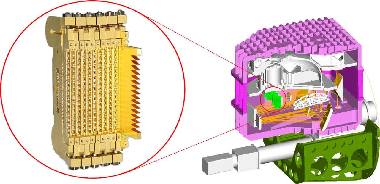
Abb. 3-8 Rechts: Schnitt durch den Kryostaten von FIFI
LS (Gesamthöhe 1 m). Im rosa dargestellten Vakuumgefäß sind die
optischen Komponenten mit Teilen des Strahlenganges sowie die Behälter für
Kühlmittel zu erkennen. Das Instrument wird mit der grün dargestellte
Halterung am Flansch des SOFIA-Teleskopes befestigt. Das optische
Nachführsystem ist als graue Röhre unter dem Vakuumgefäß dargestellt. Links:
Foto von 11 Detektormodulen des langwelligen Kanals.
Fig. 3-8: On the right side a solid
model of FIFI LS is shown (total height 1 m). The pink structure is the
cryostat shown with a cutout so the optics, optical rays, and cryogen vessels
can be seen. The green cradle is used to support the cryostat when it is
attached to the SOFIA telescope flange. The grey tube is the optical guiding
camera. Left is a close-up photograph of 11 detector modules for the long
wavelength channel.
|
|
Mit der Inbetriebnahme einer
Flüssigphasenepitaxie-Zentrifuge sind wir obigem Ziel jetzt erheblich näher
gekommen.
Die Anlage wurde von uns im vergangenen Sommer an der Universität von
Kalifornien in Berkeley aufgebaut und wird gemeinsam von MPE und UCB
betrieben. Seit einem Jahr finden Probeläufe zur Einstellung der
Betriebsparameter statt. Detaillierte Untersuchungen an den jeweils
gezüchteten Schichten erfolgen unmittelbar im Anschluss an die Herstellung in
den Labors der Partner, dabei werden unterschiedliche Messverfahren
eingesetzt. Das Programm des kommenden Jahres wird sich auf die Erlangung
extremer Materialreinheit und optimierter Kristallstruktur konzentrieren.
|
Having
set-up a new liquid phase epitaxy centrifugal growth facility at the
University of California Berkeley, we contributed an important part to reach
our goal. The centrifuge will be operated by MPE and
UCB. For one year growth runs are carried out to adjust operational
parameters. Detailed investigations of the grown GaAs samples are performed
in the laboratories of the partners with different characterization methods.
Prime importance of the development program of next year has the production
of ultra pure GaAs material with optimized crystallographic properties.
|
|
Das ISO-Spektrometerdatenzentrum (ISOSDC)
am MPE unterstützt in Zusammenarbeit mit Instituten in Groningen und Leuven
die Nutzung und weitere Verbesserung der Datenbasis der ISO-Mission. In
diesem Jahr wurde die letzte Version der "Pipeline"-Software zur
automatischen Auswertung der SWS-Daten an das ISO-Datenzentrum in
Villafranca, Spanien, abgeliefert. Die Reprozessierung der ISO-Daten zur
Homogenisierung des ISO-Archivs hat dort bereits begonnen. Die dritte Version
der offenen SWS Interactive Analysis Software (OSIA), die Wissenschaftlern
die Reduktion der SWS-Daten an ihren Heimatinstituten erlaubt, wurde
fertiggestellt.
Außerdem wurde auf Wunsch der wissenschaftlichen Gemeinde das ISO Spectral
Analysis Package (ISAP) weiterentwickelt. Das ISO-Handbuch zur Dokumentation
der Eigenschaften von Satellit und Instrumenten wurde vervollständigt.
Parallel
dazu hat die Planung der aktiven Archivphase von ISO zusammen mit den anderen
Datenzentren begonnen. Sie wird bis Ende 2006 dauern, mit dem Ziel optimalen
Zugangs zu den ISO-Daten für die wissenschaftliche Analyse und die
Vorbereitung der Folgeprojekte SIRTF, ASTRO-F und Herschel.
|
The ISO Spectrometer Data Centre
(ISOSDC) at MPE suppports in collaboration with institutes in Groningen
and Leuven use and further improvement of the ISO database. This year the
final version of the pipeline software for automatic processing of SWS data
has been delivered to the ISO data centre in Villafranca, Spain. Reprocessing
of the ISO data has already started there for homogenisation of the ISO
archive. The third version of the Open SWS Interactive Analysis software
(OSIA), allowing scientists to process SWS data at their home institutes, has
been completed. In addition, development of the ISO Spectral Analysis Package
(ISAP) has been extended on demand of the scientific community. We have
contributed
to completion of the ISO handbook documenting satellite and instrument
properties. In parallel, planning for the active archive phase has been
started in collaboration with the other data centers. This phase will last
until end of 2006. Its goal is optimal access to the ISO data for scientific
analysis and preparation of the subsequent projects SIRTF, ASTRO-F and
Herschel.
|
|
Das UCB/MPG Center for International Exchange in Astrophysics
and Space Science ist eine gemeinsame Einrichtung der MPG und der
University of California, Berkeley. Ziel ist die Zusammenarbeit auf allen
Gebieten der Astrophysik, Astronomie, und extraterrestrischen Forschung.
Wissenschaftleraustausch, Arbeitsaufenthalte und Konferenzen werden ergänzt
durch gemeinsame Projekte wie SOFIA und die Detektorentwicklung für das ferne
Infrarot. MPE koordiniert dieses Projekt von sieben Max-Planck-Instituten. Im
Jahre 2001 gab es etwa 30 Besuche von Max-Planck-Mitarbeitern an der UCB und
umgekehrt.
|
The UCB/MPG Center for
International Exchange in Astrophysics and Space Science is a joint
project of MPG and University of California, Berkeley. Its goal is
cooperation in all fields of astrophysics, astronomy and space sciences.
Exchange of scientists, visits and conferences are supplemented by joint
projects like SOFIA and the detector development for the far-infrared. MPE is
coordinating this project of seven Max-Planck institutes. In 2001, there were
approximately thirty visits of Max Planck staff to UCB and vice versa under
the auspices of the program.
|
|
DLR fördert Herschel/PACS (50 OF 9901 1 and 50 OF
0101) und das ISO-Spektrometerdatenzentrum (50 QI 9402 3). Die europäische
Union unterstützt die Projekte Laser Guide Star und POE (CT96-0094,
HPRN-CT-2000-00138). Unsere Zusammenarbeit mit der Universität Tel Aviv wird
mit einem GIF-Grant (I-0551-186.07/97) gefördert. ESO unterstützt das Projekt
CONICA (35685/VLT/91/7843). Wir erhalten Unterstützung der Verbundforschung
für ISO und Lucifer (50 OR 9913
7 und 05 AL9EE1 7).
|
DLR supports Herschel/PACS (50 OF 9901
1 and 50 OF 0101) and the ISO spectrometer data center (50 QI 9402 3).
The European Union supports the projects Laser Guide Star and POE (CT96-0094,
HPRN-CT-2000-00138). Our collaboration with Tel Aviv University is supported
by a GIF grant (I-0551-186.07/97). ESO supports the CONICA project
(35685/VLT/91/7843). We receive support from Verbundforschung for ISO and
LUCIFER (50 OR 9913 7 and 05 AL9EE1 7).
|