System
ARGOS will be widely spread over the LBT. The main elements in the system are the laser units, the launch system, and the wavefront sensors.
- The laser units contain all the hardware that is required to generate the laser beams, steer them to the required position, control the polarization, and deliver them to a common pupil location.
- The launch system expands the beam before it is folded with two large mirrors toward sky.
- A dichroic beam splitter in front of the AGW unit separates the green laser light from the science path. The laser light is then folded into the wavefront sensor unit.
- Within the wavefront sensor, according collimation and fold optics send the light through the optical shutter and onto the Shack Hartmann detectors.
- An appropriate instrument control system connects the devices among each other and ensures the operation.
- The adaptive-optics real-time control takes the signals from the wavefront detectors and the tip-tilt sensor, and steers the LBT-adaptive secondary mirrors. System-internal real-time loops ensure the position stability of the laser beacons on the wavefront sensor.
- Laser unit: behind the platform of LUCI and mounted between the wind braces
- Launch mirror: on the top of the secondary mirror
- Wavefront sensor: on the derotator structure
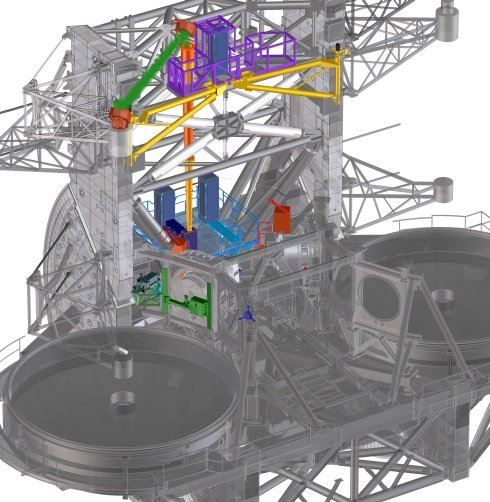
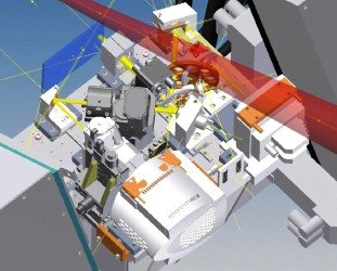
The parts of ARGOS are colored (not complete on DX).
The basic functional scheme of the whole ARGOS system is not very different to any other Rayleigh-guided adaptive-optics system:
A main time base in conjunction with electronic delay generators synchronizes the whole process of laser firing and detection. After the main trigger and appropriately tuned delays, all laser heads will simultaneously fire a pulse with ~ 20–30 ns duration. With the pulses propagating through atmosphere, a small percentage is scattered by molecules on its path. Opening the Pockels cell shutters exactly after twice the time of flight to a 12 km distance, and closing again after 2 µs, collects the photons on the detector out of a 300 m long column at that distance. With the lasers being triggered at a 10 kHz rate, the shutter will be opened in front of the CCD ten times before the accumulated image is transferred to the frame storage area of the detector. Reading the CCD thus occurs at a frame rate of 1 kHz. The transferred image then will be preprocessed for dark and line-to-line variations, and sent to the slope computer, measuring the centroids in the subapertures. Those are transferred to the adaptive secondary for reconstruction and mirror setting.
Launch system
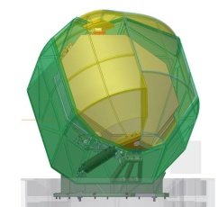
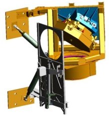
A laser launch telescope (LLT) associated with each eye of the LBT serves to expand three laser beams and relay them from the laser box to the sky.
In the picture on the left, you can see the launch mirror above the secondary mirror. The right figure shows the large lens and the folding mirror on top of the beam expander tube.
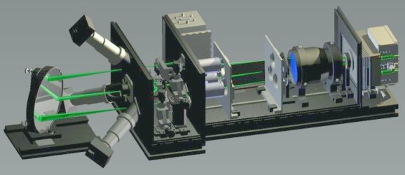
Laser system
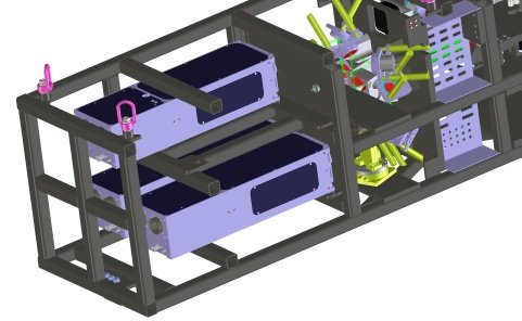
Here you can see the layout of lasers, preoptics, diagnostics, and entrance of the launch telescope.
Tip-tilt control
As the light path from the laser up to the emission level and back down to the telescope is almost identical, the tip-tilt signal will cancel out. Consequently, it is important to have a rapid tip-tilt signal available to take out this low-order, but potentially high-power effect. The tip-tilt sensor will be placed on the on-axis first light wavefront sensor board, the so-called "W-unit," developed by the Arcetri group.
Wavefront sensors
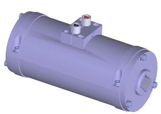
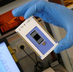
Here you can see two critical components of the wavefront sensor. The wavefront sensor detector (upper right, pnCCD) and the gating units (upper left, Pockels sell).
The middle picture shows a draft of the sensor design.
Software and real-time control
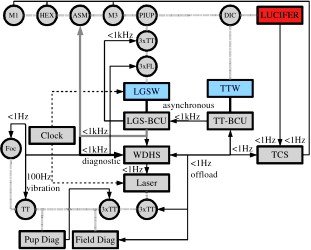
This sketch illustrates the control loop design.