Specifications
| In the table below are listed the main criteria which the laser beam from PARSEC must meet. | |
| Specification | Rationale / Comment |
| Output power: >10W (goal >15W) |
There should be the equivalent of at least 106 photons/sec at the Nasmyth focus so that the AO system is not photon limited, even in `poor' conditions (e.g. low sodium column density). |
| Spatial mode quality: M2<1.3 td=""> |
Having the beam close to diffraction limited is needed so that it can be injected into the fibre relay that takes it to the launch telescope, and also so that the smallest possible guide star is produced. |
| Linewidth: single frequency or a multi-line envelope <500mhz td=""> |
Infact PARSEC will produce a single frequency beam, which will be broadened into 4 separate lines in the beam relay system entrance to assist in transmitting the high power beam through the fibre and also to avoid saturating the sodium layer. |
| Frequency jitter: <100mhz td=""> |
This is to ensure that the frequency stays close to the centre of the absorption profile of the sodium atoms, so that the guide star is as bright as possible |
| Optical table size: 1.5m x 1.8m |
The laser room itself is only about 6m x 2.5m, so the size of the optical table is very limited; and a large part of it is reserved for the beam relay system entrance module. Further, there will only be about 70cm space to the laminar airflow unit above the table. |
| Space for electronics: 2 standard racks |
This is another difficult criterion to meet, especially since the power supplies for the pump lasers take up most of one rack. |
Additionally, and perhaps one of the hardest criteria to meet, the laser must work every night for a week without anyone going into the laser room. This means that it must be possible to carry out any necessary tuning or alignment procedures remotely, from the telescope control room.
| top of page |
Overview
An important consideration in the choice of laser type was that we want to be able to take it to the telescope as soon as possible and begin using it for astronomical observations. From all the available options, there is only one that will allow us to do this, and that is dye laser technology.
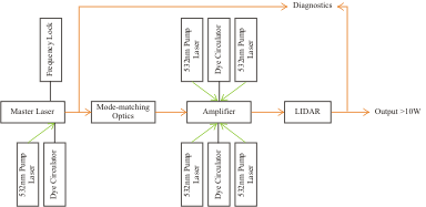
The PARSEC laser is based on the laser used in ALFA, but uses a master oscillator providing a low power high quality beam to seed a power amplifier which boosts the output power to that required.
 |
The master laser is a modified commercial ring dye laser which has a single dye jet pumped by a single 10W 532nm (green) solid-state laser. This is very stable, and can easily produce a high quality 1.5W beam. The final pump laser mirror and the output coupler are motorised so that, when the operator in the telescope control room decides, the laser can be automatically aligned.
A string of mode-matching optics then ensure the beam has the correct properties (diameter, divergence) for the amplifier. Of course this also includes a shutter and mirrors which can be moved into the beam to direct it to diagnostic devices.
The amplifier is a novel construction and has two dye jets, each of which is pumped with 2 of the 532nm lasers, one from each side. As for the master laser, the final mirrors for each of the 4 pump lasers are motorised and can be automatically aligned whenever necessary. Since there do not have to be any frequency selecting optics in the cavity (as there must be for the master laser), the amplifier is very efficient. We have measured a conversion efficiency of more than 40% from the green 532nm pump light to the 589nm orange light.
One of the crucial parts of the system is phase-locking the amplifier; that is ensuring that its length is absolutely stable (to 0.1nm) so that it resonates at the same frequency as the master laser. This is achieved in a 2-stage process. First an additional red laser beam is used to stabilise the cavity length. Although this initially seems more complicated, the main advantage is that for this laser the amplifier cavity is passive - i.e. it is unaffected by the presence of the dye jets of pump beams - and so is easier to stabilise. A longer integration time can then be used for the second phase-locking loop on the noisier signal from the orange beam.
The last stretch of the beam path includes, of course, more diagnostic devices and finally the output shutter.
| top of page |
Bench Layout
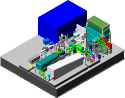
Fitting this onto the small optical table is not straight forward, and the beam must fold back and forth many times.
 |
The large blue box at the back right side is the entrance module for the Beam Relay System, which transports the laser beam to the launch telescope, and is not part of PARSEC. PARSEC itself consists of the optics mounted on the 3 baseplates, together with a pump laser module and an amplifier resonator.
The largest base plate, at front left, holds the master laser (grey) and its pump laser (green/blue). Between them is a 594nm HeNe laser which can be used for initial alignment of the master laser, for example after changing a cavity mirror. The other component on this board is the sodium cell, which is used to lock the frequency of the laser. The next board to the right is extremely crowded and contains the intermediate optics. This includes some steerable mirrors which stabilise the beam position and pointing; the option to divert the master beam to diagnostics; a zoom expander and mod-matching lens which adjusts the diameter and divergence of the laser beam to that needed by the amplifier. The amplifier is the complex and compact structure at the front right of the table. It has two dye jets, each pumped by two pump lasers (the blue/green units in the frame behind it) from opposite sides. The output power can then exceed 15W. The beam exits the amplifier back on to the central baseplate where a beam conditioner adjusts its properties to those needed at the interface with the beam relay system. After this is the LIDAR module (the vertical grey structure) which, when required, can modulate the amplitude of the laser beam very fast so that it is possible to measure the height and profile of the sodium layer. The final optics include more steerable mirrors, and other pick-offs for diagnostics, including absolute power, relative power, polarisation, line jitter and width.
The space at the back left of the table is not empty. It will hold the 'connector panel', through which all electrical signals from the bench to the electronics racks will pass.
| top of page |
Dye Circulator
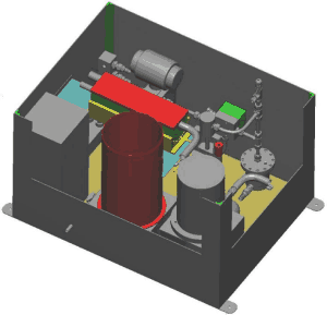
An important part of the system whic has not been mentioned yet is the dye circulator. This must pump the dye solution to all 3 nozzles at a high pressure, while allowing the jets themselves to maintain a high optical quality.
 |
Most commercial dye circulators operate at a pressure of about 5 bars. What allows us to work at 30 bars, and avoid problems associated with the dye forming a froth, is the micro-bubble remover (red box on the left side). This removes the bubbles before the dye solutino drains back into the reservoir (large red pot). The large grey cylinder in the lower right is the gear pump, and the components at the top left are the 3 valves, one to each nozzle. In between are a vriety of parts including filters, and two vibration dampers - reducing vibrations to an absolute minimum is critical if the laser is to be stable.
The circulator will sit underneath the optical table, and can be accessed through two panels.
| top of page |